Dynamic Element Matching for TDA1541 and TDA1541A
Dynamic Element Matching for TDA1541 and TDA1541A by Henk ten Pierick
Introduction
The TDA1541 contains a 10bit passive current divider and a 6 bit dynamic current divider for each channel. The dynamic current divider uses dynamic element matching to reach the required accuracy. The coarse current divider consists of cascaded divide by two cells which are interchanged with a duty cycle which must be exact 50%. Now the errors of the passive coarse current divider are averaged, which is first-order noise shaping. A full explanation is given in the Philips Semiconductors data book and in ‘Integrated Analog-to-Digital and Digital-to-Analog Converters’ by Rudy van der Plassche.
The DEM-oscillator.
The oscillator driving the shift register in the active current divider, the DEM circuit, is an emitter coupled multi vibrator. Between the emitters of this multi vibrator is a capacitor. Crosstalk into the DEM-oscillator causes the duty cycle of this oscillator to deviate from the required 50%. Measuring the current through the DEM capacitor with a current probe showed this cross- talk to be data dependent. In the TDA1541 this capacitor was brought internal which reduced cost but not solved this problem. To our benefit, the DEM-capacitor pins are still bonded out and found on pins 16 and 17. These pins are labelled to be n.c in the data sheet but they are con- nected. This can be checked with an oscilloscope which shows the expected oscillator triangular waveforms.
The DEM-oscillator frequency
The original frequency was chosen to be 100-200kHz. Interference of this frequency, caused by the data, gives idle tones. Making the DEM frequency a multiple of the sampling frequency causes all errors to fold back on DC. This is why DEM clocking improves the sound. The DEM frequency should be made such that within one sampling period all ALL DEM states are used. This brings us to the choice of 4fs or 8fs, dependent on the speed of the circuits. From this it is clear that clocking the DEM circuit is useful for over-sampled as well as non-oversampled circuits. Over-sampled DAC’s require a higher DEM clocking frequency which is not always possible. However, DEM clocking always improves the sound.
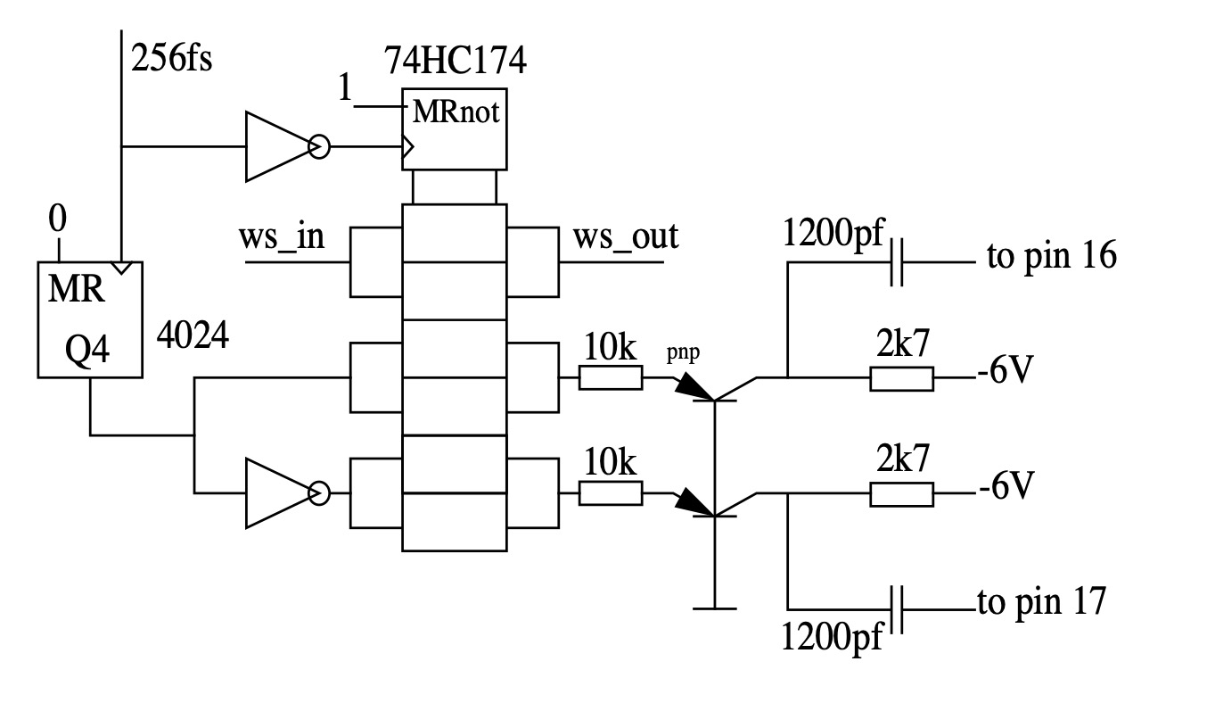
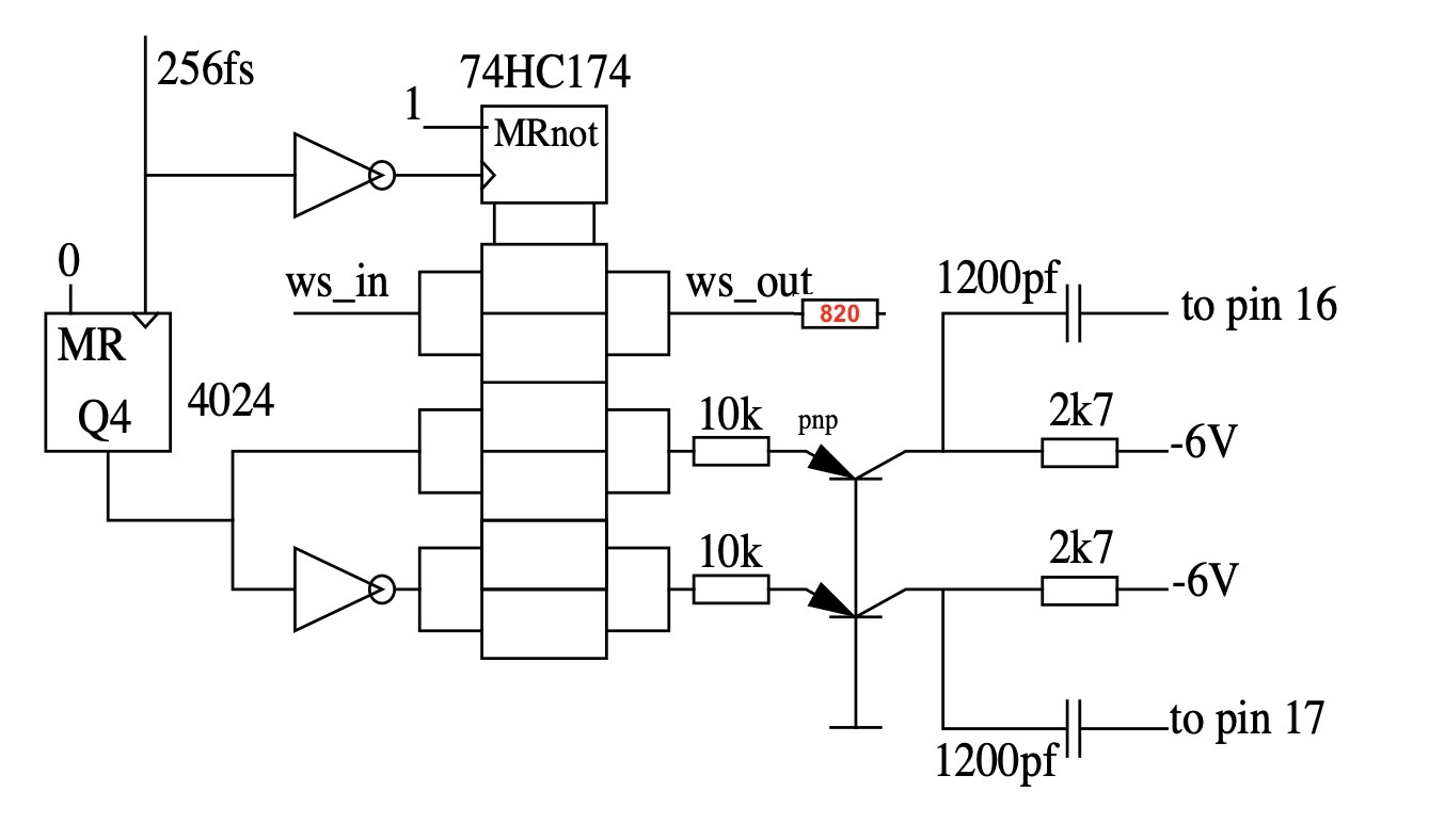
The circuit
The circuit has to take over the tail currents of the integrated emitter coupled oscillator which are 200uA. The 10k resistors will give 500uA which gives the required drive. An ac-coupling is chosen because the 200uA is process and temperature dependent. The collector supply for the pnp’s is chosen from the existing -6V in my Philips CD960. In the TDA1541 data sheet -5V is specified. The dc-value of the DEM-pins is about -9Volts resulting in only 4V reverse bias at start-up. The collectors of the switching transistors do not saturate, I used pnp switching transistors but expect that BC558’s also can be used. The capacitor at the DEM-pins, if there, is removed. The 200uA of the current sources in the TDA1541(A) cause some sawtooth on the 1200pf caps. The sawtooth may not cross the threshold voltage of the original DEM oscillator, it is not allowed to oscillate. In my CD player the WS/LE pin was determining the timing of the input latches, there for I re- clocked that word select. In other players (yours?) the BCK sets the timing of these latches, in these players the BCK should be re-clocked.
Testing
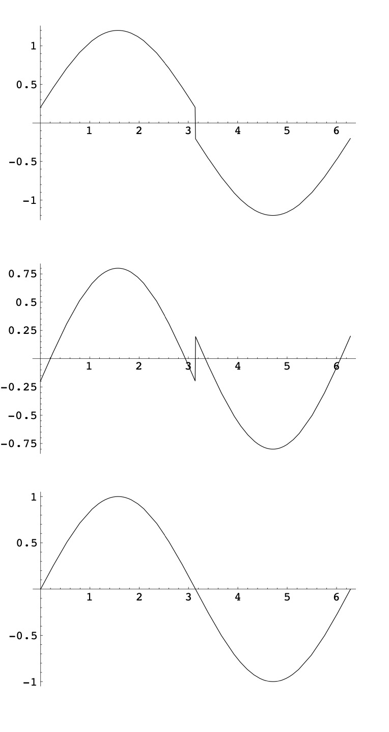
Apart from listening to music, the ultimate test, something can be measured. Using a test signal at about -40dB makes use of
both the passive and the active current divider. If there is a non-linearity here, we can measure this as crossover distortion
if the error has a fixed phase with the test signal. Otherwise is will have the crosstalk modulated difference frequency between DEM and sampling frequency. The pictures at the right are calculated but have been measured with the oscilloscope. The TDA1541(A) has some temperature effects but after 20 seconds the chip is isothermal and no effect a seen. With synchronous DEM clocking no crossover distortion is seen or measured on all chips I tried. Measuring the artifacts of a free running DEM oscillator is with a spectrum analyser or a wave analyser is a problem because of the required low resolution bandwidth. The data dependent crosstalk modulates the frequency. This has as result
that to less energy is captured in the low bandwidth.
Bron Internet -Henk ten Pierick
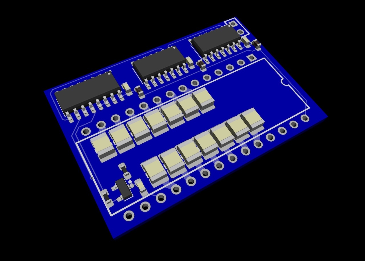
Edit : 2026-07-20 build a test board
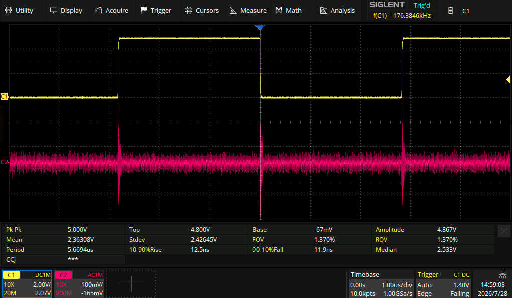
Added Resistor in Wordclock to TDA1541a , TTL out from 74hc174 is causing spike on DEM Decouple pins
- Yellow : Wordclock PIN 1 TDA1514(a)
- Purple : Signal on DEM-Decouple/filter pin
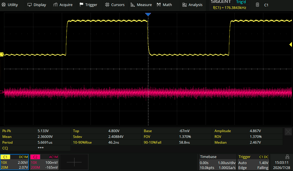
After Adding serie resistor to WC pin 1 TDA1514(A) , the spikes are gone
- Yellow : Wordclock PIN 1 TDA1514(a)
- Purple : Signal on DEM-Decouple/filter pin
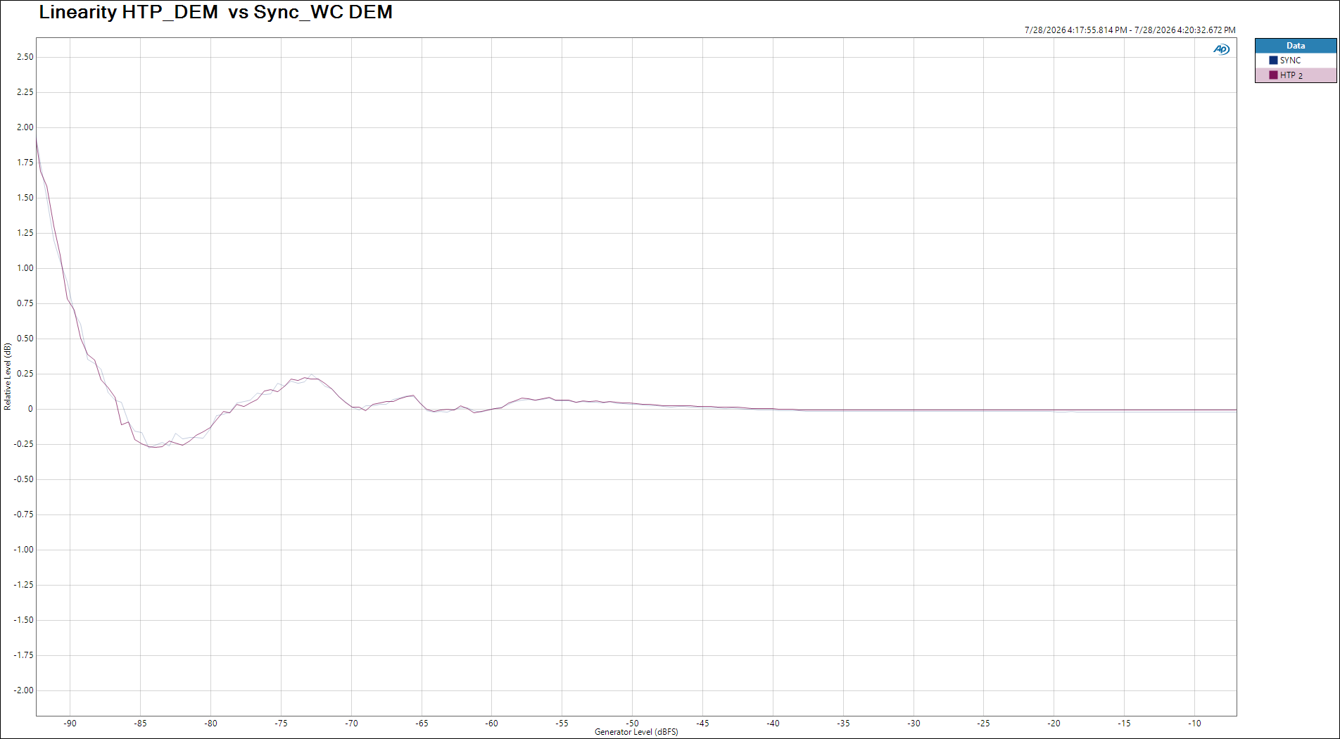
Comparison of
- Wordclock Sync DEM (Grundig DEM ) DEM Clock at 176.4 KHz
- HTP_DEM – DEM Clock Freq 706.5 kHz
Used SAA7220p/B with TDA1541A HBH9751
1 KHz – 40 dB ,16 bit dithered , Linearscale
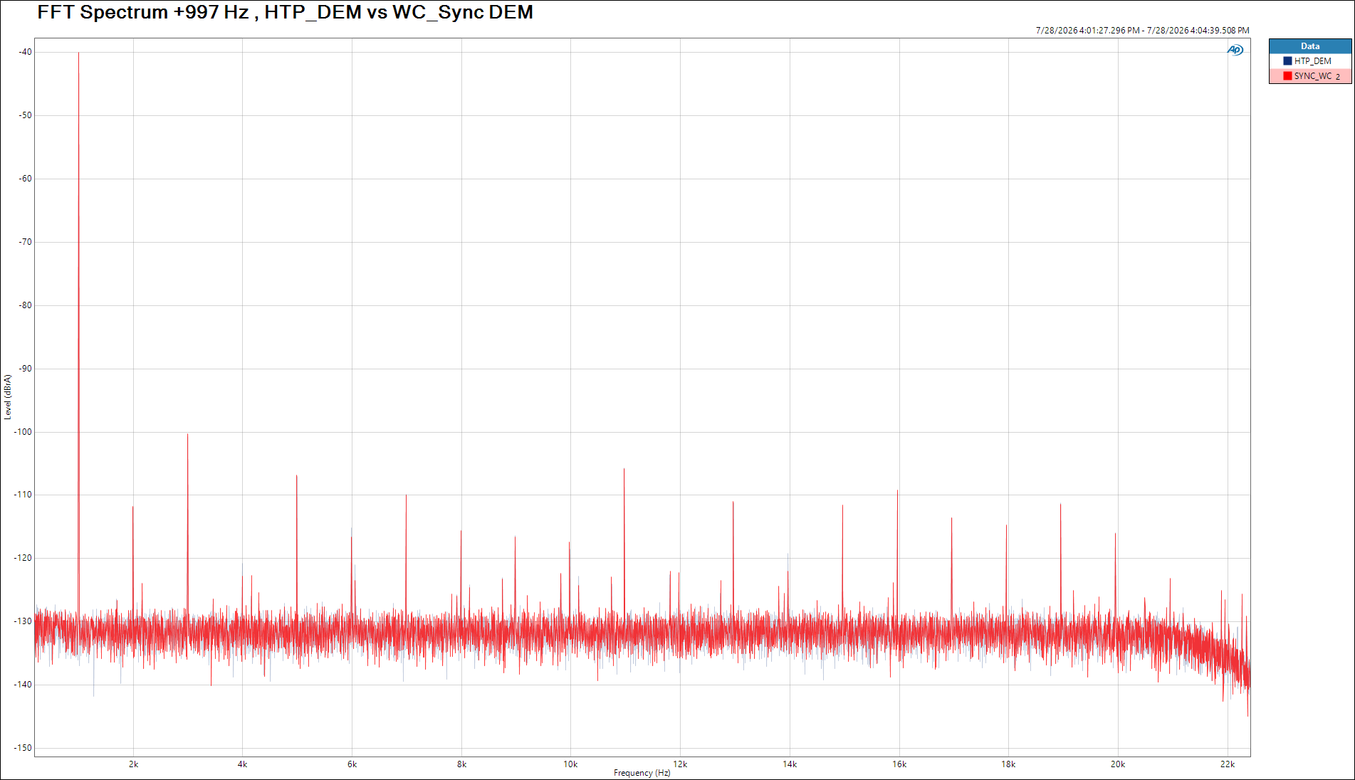
Linearity 0 dB to -96 dB